Hello everyone! I have recently received the task to connect a Brocade SN6000B switch to an existing switch fabric, so I thought I would write a article on how to do this since there are a lot of contradicting articles and not so clear articles online.
So let’s do this, step by step style! So here we go!
Before we go into the logical configuration, we need to make sure that we have the correct modules and cables connected between our switches.
If the switches are close to one another, we can use a standard SW (Short Wave) module with a minimum of a OM3 (Blue) cable or Multi-Mode cable.
If our switches are in different locations and the distance is over 400m or 1300ft or 0.2mi (yeah I love that distance conversion), we will need to use a LW (Long Wave) module, which in general has as blue latch, and to use SM cables (Single-Mode) for long distances.
Usually we would connect the same port number on both switches, but that’s not required.
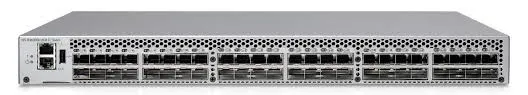
The physical connection would look like this:
Switch A -> Port 15 to Switch B -> port 15 where again the modules are the same and the cables are the same. If you are using patch panels in the middle, make sure you are connecting to the correct ports.
OK! So now that we have our physical connection in place, let’s go into the Brocade and configure those ports.
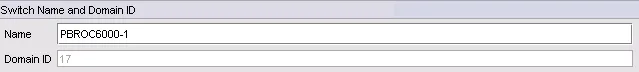
Another very important step is to make sure the Switch ID is different from the others. In my case, the other IDs are 115 and 116, so we will give this one another ID of 17 for example.
Now let’s see how we do that.
Well first of all, we need to go to the Web Management for our Brocade switch which is usually https://ip_address (change ip_address with your own IP, duh!) and login.
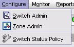
Once there, we go to Switch Admin.
Now under Domain ID, we change the domain ID to whatever we would like, but different from the other switches.
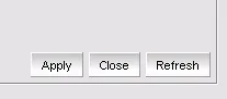
Ok, now let’s click Apply and let’s restart the switch.
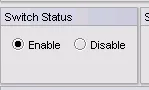
Make sure the switch is in disabled mode to be able to make this change.
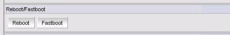
Please make sure you do a Reboot and not Fastboot.
Ok now that we rebooted the switch, let’s configure the port.
In my case I have port0 on the new switch connected to port21 on the existing switch.
Now we just need to configure each port as an E-port and then if communication is correct and so forth, they will auto negotiate which one is upstream and which one is downstream.
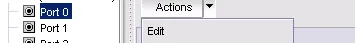
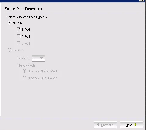
For that we right click port0 and click Edit.
Now we make sure only E Port is checked.
Now for the configuration, we mostly leave everything as default. We just change the speed to the max speed of the port. In my case it’s 8G.
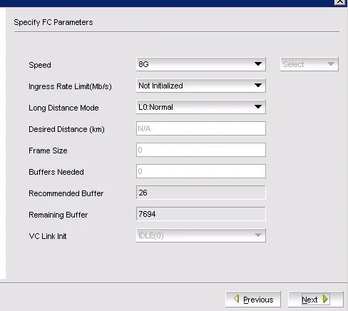
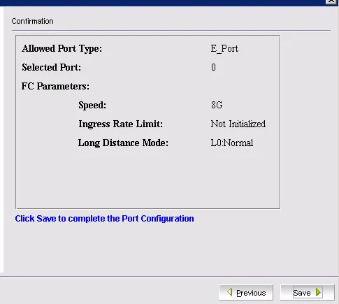
Now we click Next and on the next screen we click Save.
After this we do the exact same configuration on the other port and then we wait to get this status on each.
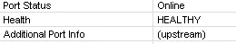
One is upstream and one is downstream.
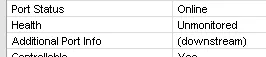
There we go, all done. Now what happens in the background is that the switch is added to the fabric and all zoning and alias configuration is copied to its database.
I really hope you enjoyed this article.